Only a few selected projects are summarized on the english website. For a more comprehensive compilation of the projects, please switch to the german website.
Only a few selected projects are summarized on the english website. For a more comprehensive compilation of the projects, please switch to the german website.
In view of the pending renovation work, the responsible building authority commissioned a comprehensive 3D building geometric survey of the church to record the skewed walls and deformations of the church vault at the Virgin Mary Pilgrimage Church in Tuntenhausen. A complete survey of the entire geometry of the building was necessary because the planning and tendering of the renovation work requires a comprehensive knowledge of the existing building geometric condition.
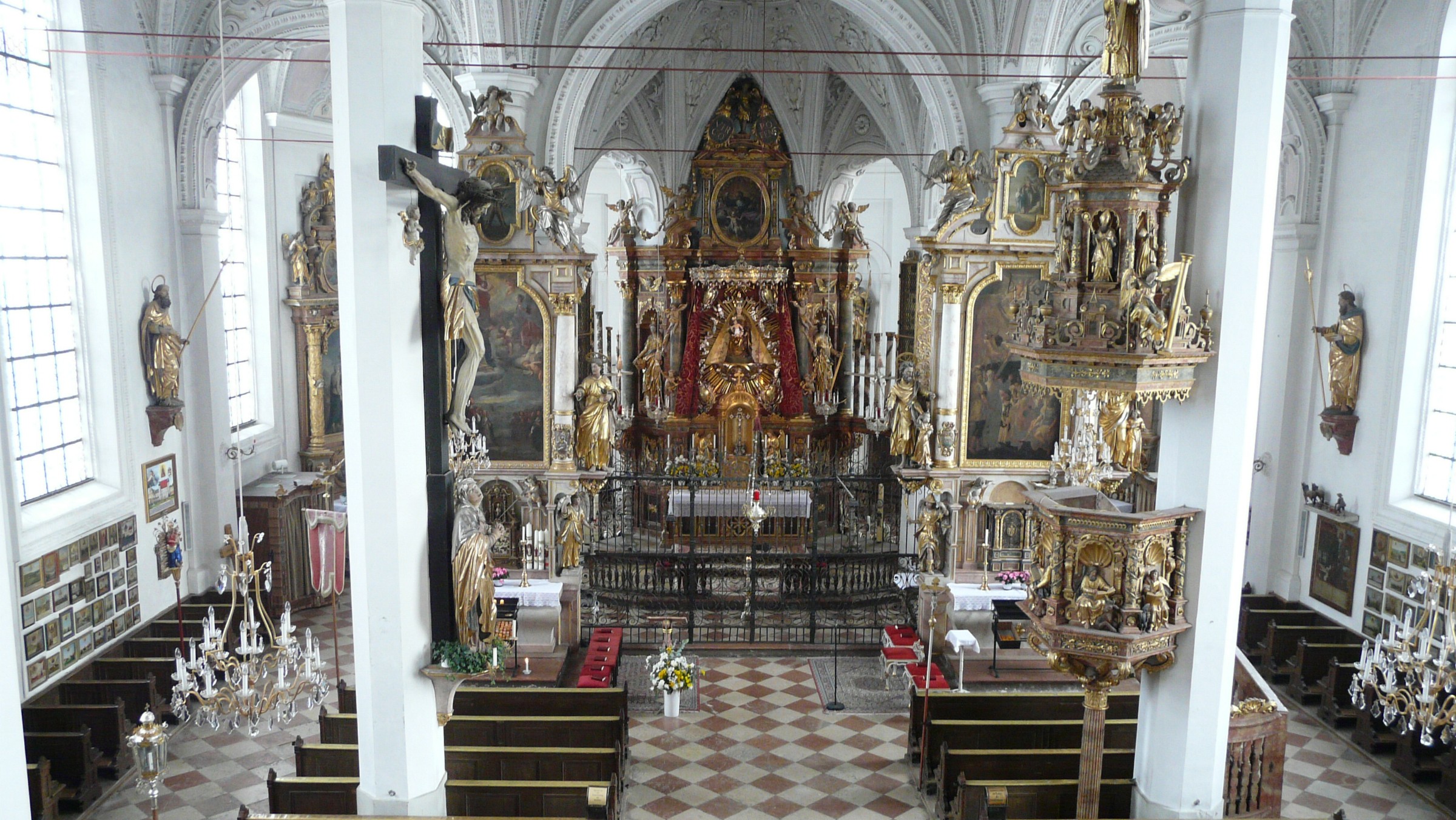
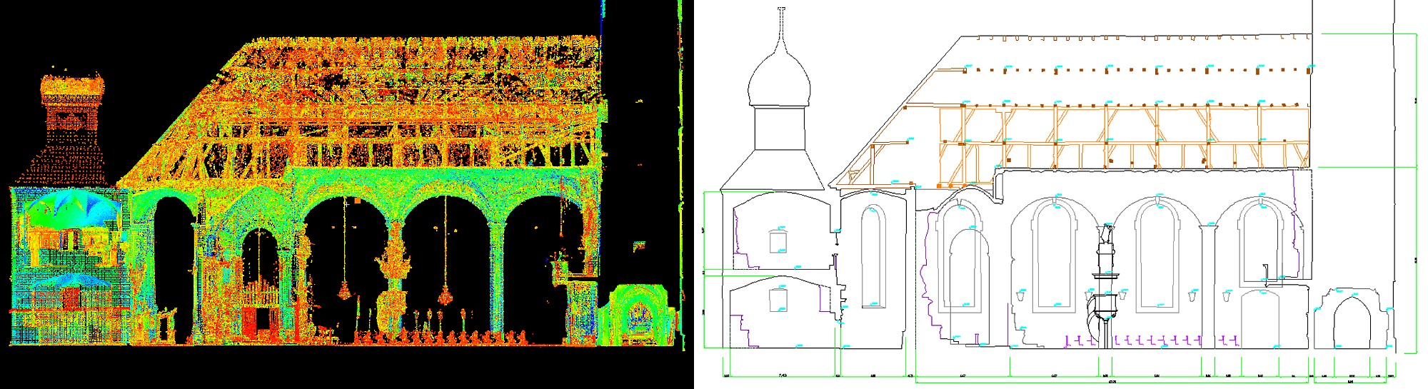
The inventory was carried out with the Imager 5006 laser scanner from the company Zoller & Fröhlich with a total of 65 positions in the exterior and interior of the church. Prior to this, a high-quality, geodetic 3D network was created using tachymetric measurements in order to be able to connect the various areas with each other. Sections can be generated from the registered point cloud, from which, for example, statements on the inclination, deformation and thickness of walls can be derived by taking measurements. With the help of an attachment camera the scans can be colored by superimposing photos.
The "GML" track measuring system was developed together with the client RISTAG Ingenieure AG, switzerland, for setting out the track geometry when installing the slab track. The GML enables a high-frequency, fully automatic and highly accurate determination of the following track parameters:
Real-time communication with routing software is important for paving in order to determine the deposits and their correction values. The correction values around which the track is to be straightened are displayed both numerically and graphically on the track measuring carriage.
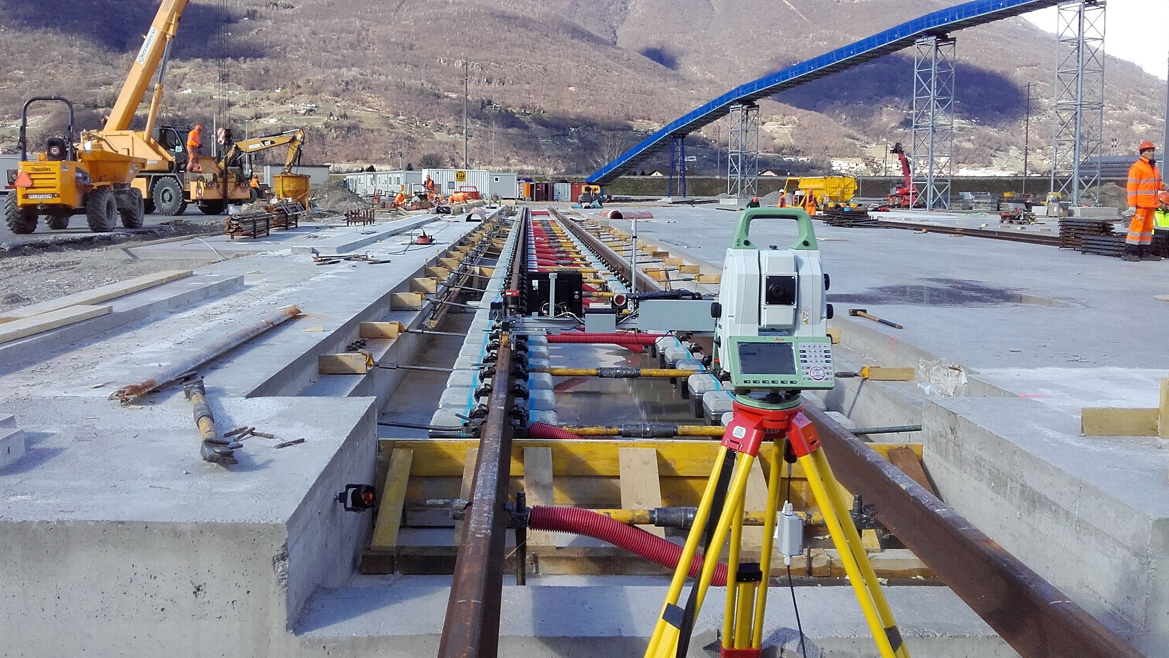
The position of a precision total station is determined by a free stationing. The position and alignment of the total station are transmitted wireless to the GML by radio. The onboard software of the GML calculates the position of the GML on the basis of the continuously transmitted polar measurement information of the total station and the current actual values of the track geometry on the basis of the other measured values from sensors on the GML itself. The comparison with the nominal values at the respective position of the track gauge results in the correction values with which the operators straighten the track before concreting.
After joint development, RISTAG Ingenieure AG successfully used GML to stake out almost 30 km of slab track.
With modern surveying gyros the north direction can be determined with an accuracy of about 1 mgon. A fully automated single measurement lasting about 10 - 12 minutes requires a vibration-free and temperature-stable environment. Multiple measurements increase the accuracy and identify any faulty measurements. In order to minimise the influence of refraction, counter-visits with the same gyroscope or mutual observations with two gyroscopes are carried out simultaneously. A typical application of the north direction determination with one survey gyroscope are orientation measurements for tunnelling control. The Institute of Geodesy could gain experience through the participation in various projects over many years, which is incorporated in research and further development of this measuring technique.
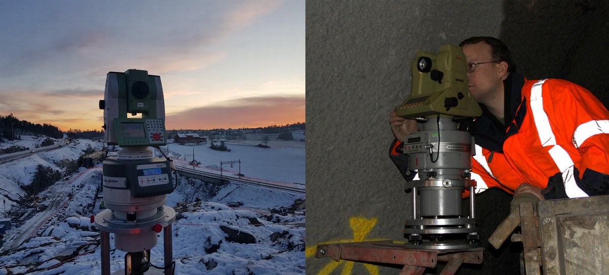
The Institute of Geodesy has two modern surveying gyroscopes, a DMT Gyromat 5000 and a DMT Gyromat 2000. The determined azimuth is related to the construction site system by means of reference measurements in the portal network. In order to ensure that a surveying gyroscope has remained mechanically stable during the measurement campaign, the calibration values of the surveying gyroscopes are determined and compared immediately before and after on the test track of the University of the Bundeswehr in Munich.
Laser trackers, such as the Leica AT-901 and Leica LTD-500 available at the Institute of Geodesy, are highly accurate and fast measuring polar measurement systems. They can be used, among other things, to record vibrations and immediately provide amplitudes in the three coordinate directions. On a valley bridge of the new railway line between Erfurt and Halle, measurements were taken during braking tests of a train to determine the deflections of the pier heads. Of particular interest are the movements in the longitudinal direction of the line in case trains have to perform emergency braking on the bridge.
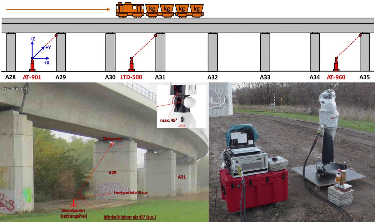
Corner cube reflectors are to be temporarily installed as target points, whose continuous movement behaviour can be recorded with a measuring frequency of 100 Hz by means of laser tracking. One laser tracker is required per target point. Despite unfavourable weather conditions during the braking tests, the movements of the pier heads could be clearly demonstrated in all test runs.
One way to determine shifts of points is to use Global Navigation Satellite Systems (GNSS). A fully automatic low-cost GNSS monitoring system has been developed for torrent and avalanche control, area construction management Außerfern and has been in practical endurance testing since 2007. With the monitoring system the course of movement of the two points located in the deformation area can be documented. In connection with further ongoing investigations and research activities, the system helps to deepen the knowledge about the movement mechanisms at Hornbergl.
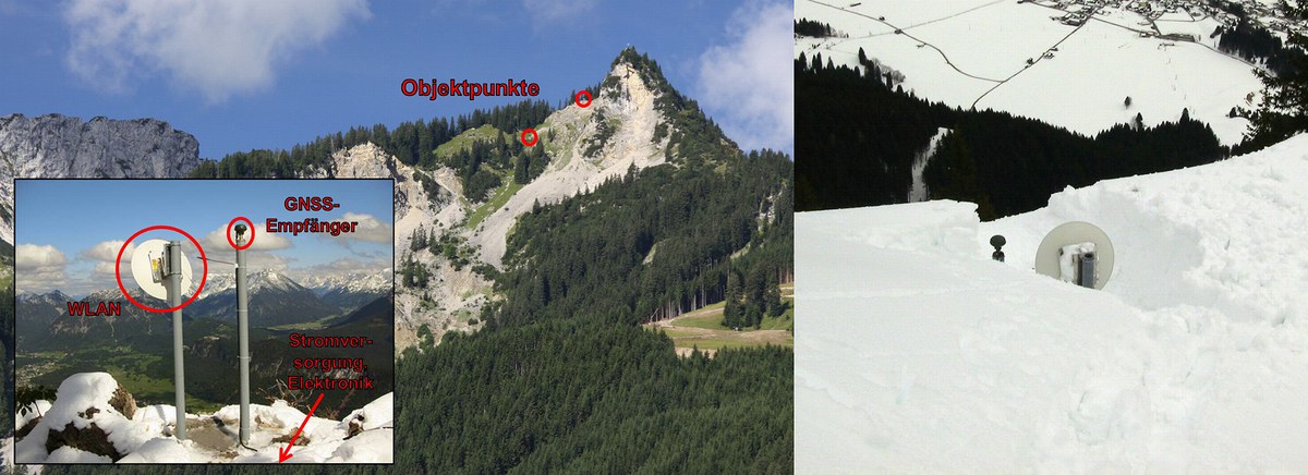
Over the years, necessary changes and updates to the system's hardware and software have been carried out time and again. From time to time, the measuring stations located on the mountainside have to be climbed on foot in order to change wearing parts or to free the sensors from snow. The latter is necessary because the antennae cannot be mounted at any height without losing stability.