For autonomous control, the two MuCAR test vehicles were equipped with actuators that enable electronic control of the steering wheel, the accelerator and brake pedals as well as the drive-mode selector. These extensions make the two vehicles fully electronically controllable (so-called drive-by-wire functionality).
The vehicle control system for the planning and execution of desired driving maneuvers is divided into two parts (see figure). The more complex path and trajectory planning (high-level control) is carried out on the on-board computer of the respective vehicle and results in a desired vehicle speed or, in certain cases, a desired stopping distance and a desired steering angle. The low-level control system is based on a simpler but very fast control system that uses the high-level commands as reference for controlling the vehicle's actuators, e.g., the accelerator.
Control Architecture
Trajectorizer
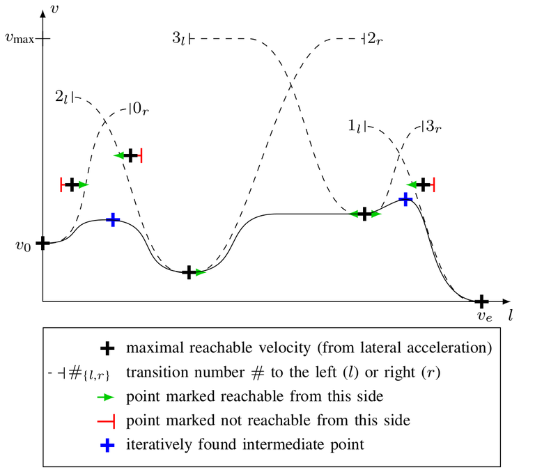
Here, paths are either converted to trajectories or given trajectories are refined. Example of a speed Profile calculation:
First, the maximum speeds, given a maximum lateral acceleration, are calculated for all path points (black crosses). Then, smooth speed transitions between pairs of points are searched for (dashed lines). In a first step, the initial speed and in the following steps, always the lowest unchecked speeds are expanded. In the above example, the first point is marked as inaccessible (red markers), the second as accessible (green markers). Unreachable points are excluded from the further search. In case of overlapping possible profiles, intermediate points (blue) are generated. Finally, a smooth speed profile is generated (continuous line).

Localizer
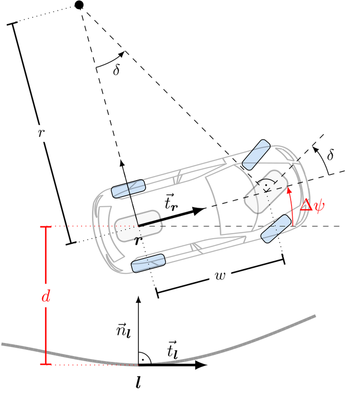
Here, the vehicle is localized on a given trajectory. Example of localization l of the rear-axle center r:
For each new egomotion estimate, the nearest point on the planned trajectory is searched for. This localization and the relative pose of the vehicle reference point are the current control errors.
Analogous to the current localization, predicted localizations are generated using past control outputs.
These predicitons are used to compensate dead times in longitudinal and lateral control.

Core
The main application uses the given trajectory and localization to calculate control commands at 100 Hz.
The algorithms used are modularly interchangeable and are selected scenario specific. Furthermore, the gear selection and emergency behavior are handled here.